This document describes the rationale behind the architecture and design of Axis2. The Axis 2 sub components are those that were finalized at the first Axis Summit held in Colombo, Sri Lanka. The document will provide a thorough understanding of the workings of a SOAP engine that is required for a developer before examining the code in detail.
Axis Java 2.0 is a SOAP engine consisting of a number of sub components. Components are identifiable with that of Axis 1.0, but the introduction of some components posses the capability of abstracting functionality to seamlessly support a number of auxiliary specifications. It is also important that the reader understands the inner workings of Axis 2 especially at component level, where dependencies and interactions between components are discussed.
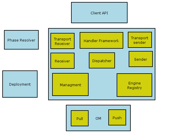
Axis2 consists of the following high level sub components, and they are described in the next section of this document.
Just like Axis 1.x family Axis2 is all about processing Messages. It is important to note that Axis2 is not just about encoding of the messages from Java to XML and vise versa. Axis is a framework for the Web Service stack. All other components WS-Security, WS-RM etc of the Web Service stack fits in to Axis via the extension mechanism of the Apache Axis. Apache Axis is a framework for Web Service Stack. Axis SOAP Message processing always starts by running the information holder called MessageContext through the extension mechanism of Axis. This builds the foundation for Axis so as to give a generic framework for all the Web Service add on services.
The extension mechanism of Axis is built with two types of components called Handlers and Phases. The Phases are placeholders for the Handlers and they can be configured via the configuration mechanism of Axis. When a web service is deployed the Phase-Resolver will order the registered Handlers inside a phase and phases will be ordered according to the configurations. When a web service is invoked the Engine will preserve the order of handlers. Once the handlers are assigned to the phases the phases are invoked in the order and in turn each Phase will invoke the contained Handlers.
The Axis contains some built in Handlers that drives the service invocation, yet the user can add new Handlers via the deployment Mechanism. The new Handlers will fit in to the Phases in the Execution Chain according to the Phase rules that is specified with each Handler.
Axis starts by loading the EngineRegistry that holds the configuration of the Engine. This configuration includes the Services, Phases, order of the phases, Handlers, Phase rules for Handlers, transport and modules. It is the Deployment that creates the EngineRegistry out of the deployment mechanism. All other components of the Axis interact with the deployment via the EngineRegistry and is not aware of the exact deployment mechanism used. The default Deployment Mechanism is based on the XML configuration files, but other deployment mechanisms are also possible. For example if Axis is going to be deployed on to a device and the list of services are not going to change, one can hard code the Configuration.
Now let us focused our attention to the exact Handlers that will be invoked during execution. They are the inbuilt handlers that are explained before, the new handlers might plug in, yet following handlers are going to be there all the time.
There are six types of special handlersThese Handlers will create either an inflow or an out flow as shown in the diagram below. At the server side it will be an inflow followed by an outflow or a fault flow and in the client side out flow followed by the inflow.

<handler name="RM" ..... before="Transaction" after="Encryption" ../>This will ensure that the rules are followed and hence executed appropriately (Note: support for before and after is not implemented in M1). As far as the implementation is concerned a Phase is a ordered collection of Handlers that are arranged according to the Phase rules. This can be viewed as an improved HandlerChain from Axis 1.x.
<service name="foo">

<module ref="Authentication"/>

</service>
Please note that this would enable authentication for service foo, but is not included in M1.
There are two types of deployment in Axis2, namely, Service Deployment and Module Deployment.
Axis2 provides a J2EE like deployment (an axis archive file has to be created and dropped into the correct directory) for both modules and services. A user can deploy a module or a service as an .aar file (module1.aar, service1.aar). Module hot deployment will not be supported in M1, but will be supported in later releases. When the axis engine is started all the .aar files in the WEB-INF/Repository/modules will get deployed. But if someone wants to add a new module or service, a restarting of the engine is required after putting the new .aar file in the above-mentioned folder.
One of the key improvements introduced with Axis2 is the capability to hot deploy web services. And in this M1 release only a J2EE like deployment is supported. That is, a user has to create an axis archive file that includes all the files that he/she wants, and drop that archive file into the WEB-INF/Repository/services directory. The following three features are associated with service deployment;
The directory structure to which modules and services should deployed are:
The required directory structure for a modules archive file is as follows;
m1.aar
META-INF/module.xml
lib/
classes/
The required directory structure for a service archive file is as follows;
s1.aar
META-INF/service.xml
lib/
classes/
The structure of module.xml file is as follows;

The structure of service.xml file is as follows;

The architecture of hot deployment consists of the following components;
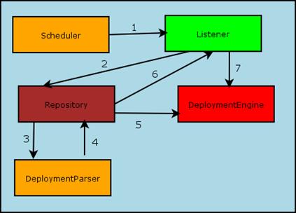
1. The Scheduler periodically invokes the Listener to check for updates
2. If the Listener finds an update, it passes that information to the Repository
3. The Repository hands over the document to the Deployment Parser
4. Having parsed the document, the Deployment Parser returns the corresponding object
5. The Repository updates the toDeploy and toUn-Deploy list
6. The Repository informs the Listener to update the system
7. The Listener informs the Deployment Engine to do the update (both deploy and un-deploy)
This component itself is a thread that performs a specific task forever in a given time interval. In this case it periodically asks the Listener to listen to the file system events. Here the file system is not the entire file system, it is only the sub directories of WEB_INF/Repository where the modules and services reside.
As mentioned above the Listener listens for file system events. In order to do this it checks both the modules and services directories. Then it lists all the archive files in those two directories and compares those against the repository to check if a new service(s) has been added or if any service(s) has been modified. Then it informs DeploymentEngine to execute the required methods.
The Repository stores data about modules and services that have already been deployed. At the initialization process this loads data about all the modules and services into the module and service directories. It then deploys all those loaded modules and services. The repository stores the name of the archive file and its last modified date. It is possible to perform the following operations to the Repository;
These operations correspond to Hot Deployment, Hot Un Deployment and Hot Update.
In the add operation it checks whether the entry which is going to be added already exists in the Repository. If so it ignores the operation else it will add the entry to the Repository and add an entry to a list maintained in the DeploymentEngine (toDeploy list).
In the remove operation it directly removes the entry from the repository and adds an entry to a list maintained in the DeploymentEngine (toUnDeploy list)
In the modify operation it adds entries to both lists in the DeploymentEngine.
The DeploymentEngine is the main component of the deployment sub component. It interacts with the axis engine and the engine registry by updating the engine registry when a new service is added or an existing service is removed. The deployment procedure is as follows;
The following three types of xml document are parsed by the DeploymentParser. Its underlying parser is StAX.
Parsing of server.xml is done as follows;
The DeploymentEngine will create an AxisGlobal object and pass that to the DeploymentParser. Then the DeploymentParser will modify the object according to server.xml.
Parsing of service.xml is done as follows;
The DeploymentEngine will create an AxisService object and pass that to the DeploymentParser. Then it will be updated according to service.xml.
Parsing module.xml is the same as above except for it been passed an AxisModule object instead of an AxisService object.
The Initialization process of the DeploymentEngine consists of the following steps:
Adding a new web service consists of the following steps;
1. Unzip the .aar file and take its service.xml and parse it using the DeploymentParser.
2. While processing the service.xml an AxisService object gets created and that object will be updated.
3. The created object is deployed to the DeploymentEngine.
4. Using the DeploymentEngine the service classLoader and the provider class will be added to the AxisService object.
5. The Handler chain will be built by resolving the phase rules.
(It
should be noted here that the Handler Chain consists of the HandlerMetadata
which has all the phase rules data and the actual executable handler )
6. The created object will be added to the EngineRegistry.
AXIOM (also know as OM Object Model) is used to refer to the new and efficient XML info set model that has been developed for Axis2. Most of the XML object models used today are based on two major methods, namely;
AXIOM gets the best from both these options and builds a better object model on top of a pull parsing methodology. It controls the phase of the parsing and builds a memory model if required from the information thats being parsed so far. That means at a given instance, AXIOM does not have a fully built object model with the rest of the information still in the stream.
The most important feature of this OM is that it is lightweight and is differed built based on StAX (JSR 173), the streaming pull parser.
The object model can be manipulated like any other object model (Such as JDOM), but underneath the objects will be created only when they are absolutely required. Hence this model is much more efficient.
AXIOM interacts with the outside world using the StAX API, that means it serializes and de-serializes using the StAX writer and StAX reader interfaces.

Since most of the data binding tools support SAX based interfaces, AXIOM comes with an adapter to be used between StAX and SAX.
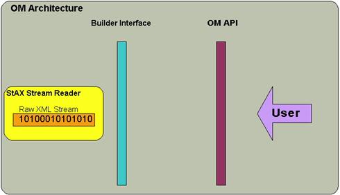
AXIOM sees the XML input stream through the StAX stream reader, which is being wrapped by a builder interface provided. Current implementation has two builders, namely;
Each of these builders has the support for differed building and caching. User has the option of building the memory model or not. He can control this via setting the cache on or off.
(Since the object model is pull based, the StAX API is tightly bound to OM. To work with OM a StAX compliant parser and the API must be present in the classpath. )
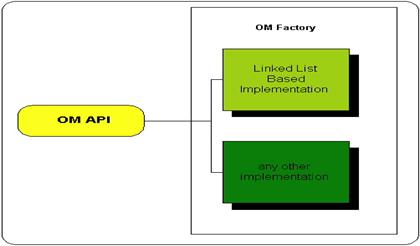
The OM API works on top of the builder interface and provides for users, be they an engine developer, handler developer or anyone else. This will provide the highest flexibility as one can change builders and object model implementations completely independent to one another.
The OM has a defined set of APIs and one can implement his/her own memory model based on that. The current Axis2, comes with a linked list based implementation of those set of APIs. (There was an effort to build another OM on a table based model. Its now on hold.)
Phase is a logically ordered collection of handlers. The handler inside a phase is ordered by phase rules. By using phase rules a user can specify where the handler should be logically placed. Some of the valid attributes associated with phase rules are listed in the following table :
|
Attribute Name |
Value |
|
Before |
Can be either a handler or a phase * |
|
After |
Can be either a handler or a phase * |
|
Phase |
Valid phase name ** |
|
PhaseFirst |
Boolean *** |
|
PhaseLast |
Boolean *** |
* - If the before or after attribute of a handler is another handler, then the referenced handler must belong to the same phase. If the before or after attribute is a phase, there cannot be a phase attribute of that handler. If one of before or after is a handler other can not be a phase.
** - valid phase is a phase that is listed in the server.xml. If the phase name is not there then the phase name is not a valid phase.
*** - If both the PhaseFirst and PhaseLast attributes of some handler are true, then the case phase only has one handler.
N:B : If the user is going to use handlers and attributes as before, then there is no need to use PhaseFirst and PhaseLast because those are ignored by the rule engine.
The Handler chain is a collection of phases and handlers. The order of phases in the chain is described in server.xml. One service can have three handler chains;
For each and every handler chain, handlers can come in different ways as follows:
WSDL Module of Axis2 was architected with both WSDL version 1.1 and version 2.0 Component model in mind. The entire architecture of the aforesaid Module is built around an Object Model called WSDL Object Model which will be referred to as WOM here fourth.
WSDL Module can be mainly broken down into two major functionalities:
Service Description will provide an API to the Axis2 Engine that will expose
the sufficient statistics about the web service that has been described in the
WSDL file. WSDL Processing basically involves WSDL2Java, WSDL24J, and Java2WSDL.
Following sections will give a further overview of each of the above
functionalities.
WOM is engineered based on WSDL 2.0 component model, but it does not restrict
its functionality to prior WSDL versions. Rather both WSDL 1.1 and WSDL 2.0
versions will be supported on top of the WOM. WOM consists of components such as
Description, Interface, Service, etc. All those Components extend from one super
interface called org.apache.wsdl.Component which will prove to be very useful in
the implementation of the Service Desc.
WOM is a runtime representation of the WSDL file and it will provide
the web service description functionality. As the following diagram illustrate
the WOM will be the common Object model that will be used in bothWSDL2Java and
Java2WSDL functionality. This intermediary object model ease the discussion
since the WSDL processing can be broken down into the following four sub
modules.
Service Description (also known as Service Desc) is an API by which the necessary statistics will be made available to the Axis2 Engine at the runtime.
The functionality of the WOM is very much similar to the functionality expected from that of the Service Desc. Both behave as runtime description of the web service. Difference is that WOM is a clean component model that is not dependent on Axis2 or any other SOAP Engine and Service Desc is the Axis2 specific description of the web service. Thus it was necessary that the Axis Service Desc to extend the WOM to incorporate the additional Axis specific deployment information such as handlers, modules, providers, etc. The actual implementation of such extensions has been achieved using the extension capability provided by the WOM itself.
As mentioned above all the Components in the WOM extend from a super interface org.apache.wsdl.Component. Service Desc makes use of the functionality provided by org.apache.wsdl.Component to interface the WOM to behave as a Service Desc. org.apache.wsdl.Component has the following class diagram.

![]()
As the diagram illustrate the Component class provides the functionality of storing properties. Since all the WSDL Components extend from this class directly or indirectly, this functionality get inherited to all the WSDL Components. The Service Desc makes use of this functionality to store Axis2 specific properties using the WOM. In that sense the Axis2 Service Desc is a wrapper to the WOM.
Following is the Class diagram of the top level component of the description
Component org.apache.axis2.description.impl.AxisService.


![]()
WSDL Processing can be identified as of operations performed on or performed using the WOM. Such definition is made possible because of the intermediary object model i.e. WOM always acts as an intermediary state. For example if WSDL2Java is considered:
WSDL2Java = WSDL-->WOM (WSDL2WOMBuilder), WOM-->Java (Code Generation Module).
The point to note is that the above allows the WSDL-->WOM (WSDL2WOMBuilder) to be identified as an independent module, not tied to the WSDL2Java operation. There are four such modules identified in the WSDL Processing Module of Axis2.
Types of Client programming models that Axis2 support:
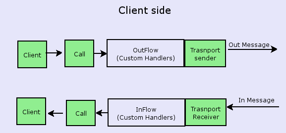
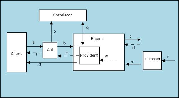
The following diagram describes all the invocations between sub components in the client side.
Call Class consist of following methods (Call API)

Callback Interface
AsyncResult
Correlator

This invocation is similar to fire and forget where a request is sent and an acknowledgement is not expected. An invocation will consist of the following steps :

Code Snippet:
Sequence diagram
The service invocation is a void invocation. There is no return value, but there is a wait for an acknowledgment or a SOAP Fault, It consists of the following steps :
a -> call.send(SOAPEnvelope)
b -> engine.send( ..)
c -> Send the SOAP message
Code Snippet:
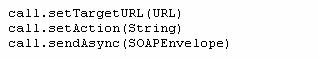
call.setTargetURL(URL)
call.setAction(String)
call.send(SOAPEnvelope)
Sequence diagram

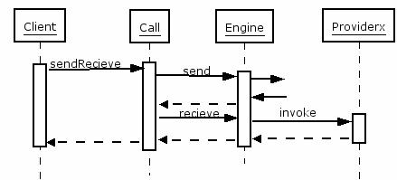
The service method has a response and the communication happens synchronously using a bi-directional protocol. The Client hangs until the response (or fault) is returned.
a -> call.sendReceive(SOAPEnvelope)
b- > engine.send (..)
c -> Send the SOAP message
d -> Receive the response over the synchronous transport
w -> ProviderX will be called as the last step in engine.receive(..)
e -> provider returns
f -> Call hand over the response to the client
Code Snippet:
call.setTargetURL(URL)
call.setAction(String)
SOAPEnvelope env=call.sendReceive(SOAPEnvelope)
Sequence diagram
The service method has a response and the communication happens synchronously using a bi-directional protocol. Client DOES NOT hangs until the response (or fault) is returned. The Client uses a callback mechanism to retrieve the response. The Call API uses threads from a thread pool for each invocation.
a -> call.sendReceiveAsync (SOAPEnvelope, callbackObj)
p -> correlator.addCorrelationInfor(msgID,allbackObjRef)
b- > engine.send (..)
c -> Send the SOAP message
d -> Receive the response over the synchronous transport
w -> ProviderX will be called as the last step in engine.receive(..)
q -> correlator.getCorrelationInfo(msgID)
g -> callbackObj.onComplete()
Code Snippet:
call.setTargetURL(URL)
call.setAction(String)
call.setListenerTransport(http, true)
call.sendReceiveAsync (SOAPEnvelope, Callback)
Sequence diagram
The service method has a response and the communication happens asynchronously using a uni-directional protocol. The Client DOES NOT hang until the response (or fault) is returned. The Client uses a callback mechanism to retrieve the response. The Call API uses threads from a thread pool for each invocation.
a -> call.sendReceiveAsync (SOAPEnvelope, callbackObj)
p -> correlator.addCorrelationInfor(msgID,allbackObjRef)
b- > engine.send (..)
c -> Send the SOAP message
r -> Receive the response by the listener
s -> engine.receive(..)
w -> ProviderX will be called as the last step in engine.receive(..)
q -> correlator.getCorrelationInfo(msgID)
g -> callbackObj.onComplete()
Code Snippet:
call.setTargetURL(URL)
call.setAction(String)
call.setListenerTransport(http, false)
call.sendReceiveAsync(SOAPEnvelope, Callback)
Sequence diagram